

For many years, measuring the ambient temperature was the gold standard when it came to determining the temperature load on components, including resistors, on a PCB. This was easy to measure, as all that was required was to attach a sensor above a PCB or inside a housing. Accordingly, more or less all resistor data sheets specified the “rated ambient temperature”, i.e. the ambient temperature at which derating begins (see Figure 1, red line).
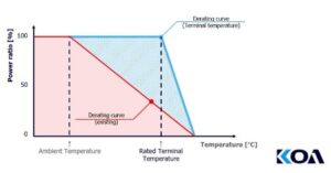
For thick-film resistors, the rated ambient temperature is usually 70⁰C, while for thin-film resistors it is mostly 85⁰C. Above these temperatures, the component may only be loaded with increasingly lower power ratings.
Everything used to be different
As simple and widespread as this temperature concept is, it does have some serious disadvantages. Measuring the temperature somewhere above the board says relatively little about the temperature conditions on or in the individual component. If, for example, the resistor is installed near a power semiconductor or a heat sink, the ambient air will certainly be heated by these and less by the SMD component.
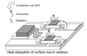
In the good old days, when THT types were still predominantly used, the principle of ambient temperature may have made sense, as the body of a wired resistor dissipates most of its waste heat into the ambient air. Resistors in SMD technology, on the other hand, dissipate a good 90% of their waste heat into the circuit board.
Maintaining the ambient temperature always required applying a reduction to the power ratings of the resistors in the data sheets. Precisely because an ambient temperature of 70⁰C says little about the heating of the SMD resistor (whose heating could be significantly higher), it was necessary to be cautious when specifying the respective rated power. As a result, larger and more expensive resistors tend to be used than is technically necessary, and space on the circuit board is wasted.
Measurement at the terminals
However, a much more meaningful measurement for SMD resistors is the temperature measurement at the terminals. These measurement results provide a realistic picture of the thermal load on the resistor. Accordingly, there is no need to reduce the rated power of the component. It is important to note the temperature at the terminals at which derating begins (see Figure 1, blue line). As a result, the component can carry a higher power than if only the ambient temperature is considered. However, if this power is not required, the use of a smaller size may also be considered.
Developers often point out that they measure the hot spot temperature of a resistor rather than the terminal temperature. Even though the delta varies depending on the size, it can be assumed that the hot spot temperature is always above the terminal temperature. As long as the hot spot measurement does not exceed the rated terminal part temperature specified in the data sheet, you are definitely on the safe side.
KOA offers both temperature concepts for many series in the data sheets. Depending on the design requirements, the appropriate measurement approach and component can be selected.
Measuring the temperature of SMD terminations is certainly more complex than simply measuring the ambient temperature. When designing circuits, it is also important to ensure that the board is not subjected to excessive thermal stress. However, the effort involved appears to be justified in terms of the potential space and cost savings.

