

SMD resistors, manufactured using thick-film or thin-film technology, are probably among the most common components on a PCB. The two technologies differ significantly in terms of manufacturing, design, and electrical parameters, with further significant differences within each technology. With a few exceptions, all KOA series presented here have been tested in accordance with AECQ-200.
Thick-film resistor structure

Aluminum oxide (Al2O3) is used as the ceramic substrate material for thick-film and thin-film resistors. In thick-film technology, the actual resistive material consists of a paste based on ruthenium oxide (RuO2), which is applied to the ceramic by screen printing and then fired. The “thickness” of the RuO2 paste is in the range of 10-14µm. Strictly speaking, the thick film paste is a mixture of RuO2 (conductive) and small glass particles (non-conductive). Different paste mixtures are used depending on the resistance series and resistance value. In order to achieve the desired, precise resistance value, the resistance layer is adjusted with a laser, a process known as trimming. Depending on the type of resistance, different patterns of incisions are possible here. The L-cut, for example, is frequently used.
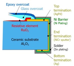 Of course, an SMD resistor also needs connections. In most cases, these consist of three layers (silver and NiCr, nickel barrier layer, tin layer), with the inner top termination (AgPd) forming the transition to the resistance layer. On the surface, the resistance layer is covered by an inner glass layer and an epoxy resin layer.
KOA thick film series
The various KOA series have very different (electrical) properties. The standard thick film series RK73 alone is available in the variants RK73B (tolerance 5%, TK 200ppm/K), RK73H (tolerance 1%, TK 100ppm/K), RK73G (tolerance 0.5%, TK 50ppm/K) and as jumper RK73Z in sizes 008004 to 2512 inch.
The SG73 series features higher rated power and, above all, pulse resistance. Depending on the type of pulse and precision requirements, the SG73, SG73P, SG73S, and SG73G variants are available.
The HV73 series is designed for higher continuous voltages. Thanks to additional internal insulation against overvoltage, a working voltage of 800V can be applied to size 1206, for example. Up to 3000VDC is possible with size 2512. Accordingly, the HV73 is also a high-ohm resistor, with values up to 100MΩ available.
The Wide Terminal Series WK73R is particularly suitable for higher continuous loads. As the name suggests, the connections are located on the long sides. Among other things, this enables improved heat dissipation into the circuit board. This means that a rated power of 1.5W is possible for size 0612 and up to 3W for size 1225.
Also worth mentioning are KOA’s low ohm/shunt series in thick film technology. In particular, the SR73, UR73V, and WK73S series. The UR73V and WK73S achieve minimum values of 10mΩ. The UR73V2B in size 1206 can handle up to 1W, while the WK73S3A in 1225 can handle up to 4W.
Finally, we would like to describe a new thick film series with special properties in terms of precision. The RS73 enables initial tolerances of ±0.1% and a TK of ±25ppm/K, values that were previously only achievable with thin-film resistors. The long-term stability of the RS73 is also exceptionally good, and the RS73 has better ESD compatibility than a thin-film component with comparable parameters.
Thin-film resistor structure
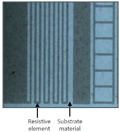
Thin-film resistors are also known as metal film resistors. Thin-film technology involves a significantly more complex manufacturing process under clean room conditions. A very thin nickel-chromium layer is applied to the ceramic substrate using a sputtering process. The layer thickness ranges between 10 and 100 nm. The final structure of the resistive element is then created using a photolithographic process. Laser trimming is then used again in the designated areas to achieve the desired resistance value.

The connections in thin-film resistors also consist of three layers (CrNiCu and NiCr, nickel barrier layer, tin layer), with the upper termination overlapping the resistive layer. Here too, the resistive layer is covered by epoxy resin layers.
KOA thin-film series
KOA’s thin-film series are not quite as numerous and varied as KOA’s thick-film series, but each series offers a large number of variants due to the broader spectrum of initial tolerances and temperature coefficients.
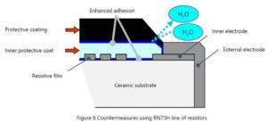
KOA’s top performer in the thin-film sector is the RN73 series. This series is available in the RN73R and RN73H variants. The lowest initial tolerance possible is ±0.05%, and the narrowest TK is ±5ppm/K. As is usual with thin film, the RN73R/H also features high long-term stability over several thousand hours. The RN73H differs from the RN73R in that it has an additional internal SiO2 protective layer against moisture penetration on the resistive material, making the RN73H suitable for demanding automotive applications (e.g., engine compartment).
If you need a thin-film resistor with higher power, you can use the wide terminal type WN73H. Here, too, the connections are located on the long sides of the resistor for better heat dissipation, and the internal structure is protected by a SiO2 protective layer, as in the RN73H. Both sizes, 0306 and 0612, are available. For example, the rated power of the WN73H2B in 0612 is specified as 1W—more than twice that of the comparable RN73H2B in 1206 with standard terminals.
KOA also offers special series in silicon-based thin-film technology, such as a high-precision voltage divider in an SOT-23 package, series name RTY. The high-voltage voltage divider network of the HVD series is also outstanding. This enables precise voltage division of max. 1000V and a division ratio of 10:1 to 1000:1.
Differences between thick film and thin film resistors
The outstanding properties of thin film resistors are undoubtedly their precision and long-term stability. Even though KOA is venturing into areas previously reserved for thin film with its new RS73 thick film series, thin film technology is still indispensable when it comes to very small tolerances and tight TCs, as well as very low resistance drift over many thousands of hours.
When it comes to transmitting signals with as little interference as possible, the metallic thin-film element offers better values. Thick-film resistors are at a disadvantage when it comes to current noise, as the granular structure of the resistor paste affects the quality of the signal. The higher the resistance value, the higher the proportion of glass particles in the paste, and the stronger the noise.
In terms of ESD and pulse resistance as well as rated power (for comparable sizes), thick-film series have an advantage over thin-film series. This is where the very robust thick-film paste pays off. As can be seen from the large number of series, thick-film resistors can be used in a wide variety of applications and are generally a comparatively inexpensive solution.

